

Quality
QUALITYContact Us
CONTACT USZHUHAI KAMEDA TECHNOLOGY CO., LTD.
Tel: +86 756 516 6177
Email: Show contact details
Add: 4/F, Block 4, No.26 XinKe 2nd Rd, Baijiao Science & Technology Industrial Park, Doumen District, Zhuhai, Guangdong, China 519100
+86 756 516 6177
Quality Control
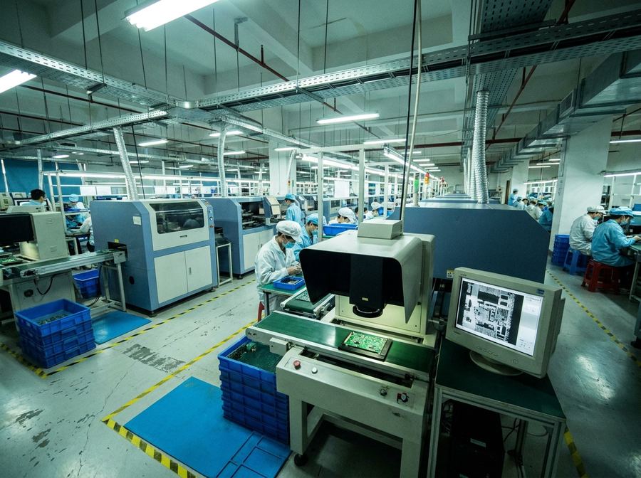
Quality is built at each operation, not sorted out at final inspection. There are check points at printing, placement, reflow, through-hole and hand soldering, and assembly, backed by AOI, X-ray, ICT, flying probe, FCT and visual inspection. When a check fails, the line stops and the cause is found before the next board is built, so the defect does not travel downstream.
Inspection and test
- AOI. Two stations, one before reflow and one after. Pre-reflow AOI finds wrong part, missing part, offset and reversed polarity at the point where rework is only a re-place, which is the cheapest moment to fix any of them. Post-reflow AOI finds tombstoning, bridging, insufficient solder, solder balls and poorly formed joints. It is fast enough to run on every board, so it is the first line of screening in volume production.
- X-ray. The only way to see joints under BGA, QFN and LGA packages, where neither the eye nor AOI reaches. It shows voiding, bridging, open joints and package offset. We X-ray the first article on every new build, sample at an agreed rate in production, and always re-inspect after BGA rework. Worth its cost on any board with area-array packages, and largely unnecessary on a simple two-sided board with no hidden joints.
- ICT. A bed-of-nails fixture contacts test points across the board and measures resistors, capacitors, diodes and transistors node by node, catching opens, shorts, wrong values, reversed parts and out-of-tolerance components. The fixture is a one-time cost and takes time to build, but the test cycle is seconds. It pays for itself on a stable design running in volume, and it needs test points designed in, which is a DFT question best settled before layout is released.
- Flying probe. Probes travel to coordinates taken from the CAD data, so no fixture is needed and a design revision means only a program change. Coverage of opens and shorts is thorough, but it tests one net at a time and is slow per board. That makes it the right tool for prototypes, small runs and verification before a design is committed to an ICT fixture.
- FCT. The board is powered up on a test fixture and exercised with a test program, either supplied by you or developed here to your test specification. It simulates real operating conditions and verifies board-level function and key parameters. FCT catches what electrical testing cannot: firmware behaviour, interface function, calibration values and anything that only appears when the board is running. It is normally placed before final assembly or before shipment.
- Visual inspection. Used at the operations that are still manual: through-hole insertion, hand soldering, coating and assembly. Operators work under magnification against your golden sample and limit samples, checking joint appearance, component orientation, markings, contamination and cosmetic damage. Trained and vision-checked before they are assigned to the station. Judgement calls on cosmetics are settled by limit sample, not by opinion.
Process control
Incoming inspection (IQC) checks part number, specification, quantity, packaging, moisture sensitivity level and physical condition on every delivery. Critical and high-value components are sampled and verified electrically. Material that fails is rejected. If a deviation has to be accepted to keep a build moving, it goes back to you or to engineering for written approval before it is issued to the line.
First article inspection (FAI) is run at every line start, changeover, reel change and program change. Process and quality both check the board against the BOM, the placement drawing and the approved sample, and both sign it off before the line runs. In-process inspection (IPQC) patrols on a fixed interval and records print thickness, reflow profile status, nozzle and fixture condition, and soldering and coating parameters. Outgoing inspection (OQC) samples each batch for appearance, function and packing.
Traceability
Each work order carries one batch number and states your part number, model, revision, build date and quantity. Material is kitted against the BOM before it is issued, and the manufacturer, date code and lot number of each part are logged against the feeder position it was loaded into. Printing, placement, reflow and test parameters, plus the inspection records, are filed against the same work order. If a problem appears in the field months later, the batch number leads back to the exact component lots, operators and machine settings used, which keeps the containment to the boards actually affected instead of the whole shipment.
What is on record
Every build leaves a paper trail: SPI and AOI results, X-ray images from the first article and from production samples, ICT or flying probe logs, FCT logs, and the signed first article record. Which of those travel with the batch, in what format and at what sampling rate, is agreed job by job before the first board is built, because a ten-piece prototype run and a repeat production order do not need the same paperwork. Ask for the list you want at quotation stage and it goes into the work instruction with everything else.
Workmanship standard
Boards are built and inspected to the acceptance class you specify, most commonly IPC-A-610 Class 2 or Class 3. Before the job is released, engineering confirms the drawings, the golden sample and the limit samples, and writes the accept and reject criteria into the work instruction and the inspection specification. Solder volume, fillet height, allowable offset and the accept/reject boundary are agreed in writing by both sides before production starts. Where you have your own internal workmanship standard, that standard governs.
| Inspection point | What it covers |
|---|---|
| IQC incoming inspection | Part number, specification, quantity, packaging, MSL and physical condition; critical components sampled and verified electrically |
| FAI first article | At every line start, changeover, reel change and program change; signed off by process and quality before the line runs |
| Pre-reflow AOI | Wrong part, missing part, offset and reversed polarity, while rework is only a re-place |
| Post-reflow AOI | Tombstoning, bridging, insufficient solder, solder balls and poorly formed joints |
| X-ray | Hidden joints under BGA, QFN and LGA: voiding, bridging and opens. First article always, production sampled, and after any BGA rework |
| Electrical test | ICT or flying probe for opens, shorts, wrong parts and out-of-tolerance values |
| FCT functional test | Board powered on a fixture and exercised under simulated operating conditions to verify function and key parameters |
| Burn-in | Powered burn-in at the temperature, duration and load you specify, to bring out early-life failures |
| IPQC in-process | Patrol checks on print thickness, reflow profile, fixture and nozzle condition and operator method, each one recorded |
| OQC outgoing | Batch sampling of appearance, function and packing before the goods are released |
| Records | AOI and X-ray images, ICT or flying probe logs, FCT logs and the signed first article record; which of them ship with the batch is agreed job by job |
| Acceptance standard | The class you specify, commonly IPC-A-610 Class 2 or Class 3 |
For a quotation, send us your Gerber, BOM and pick-and-place files — we reply within one working day.