

Services
SERVICESContact Us
CONTACT USZHUHAI KAMEDA TECHNOLOGY CO., LTD.
Tel: +86 756 516 6177
Email: Show contact details
Add: 4/F, Block 4, No.26 XinKe 2nd Rd, Baijiao Science & Technology Industrial Park, Doumen District, Zhuhai, Guangdong, China 519100
+86 756 516 6177
Through-hole assembly puts leaded components through plated holes and solders them on the far side, by wave, by selective soldering or by hand. Transformers, electrolytic capacitors, connectors, relays and high-power devices still come in that format because the joint holds up under vibration and repeated mating. Power supplies, drivers and industrial control boards are built this way for that reason.
What surface mount cannot carry goes to through-hole and secondary soldering. The insertion stations sit next to the SMT lines: boards come off reflow and go straight into insertion, are soldered by the method the board calls for, then cleaned, inspected and coated in the same building. The board does not leave the site between reflow and final inspection.
When through-hole is the right choice
- Power supplies, adapters and LED drivers carrying large electrolytics, inductors and transformers.
- Industrial control and instrumentation boards with many terminals, sockets and relays, where joints see vibration.
- Connectors, switches and terminal blocks that will be mated and unmated repeatedly in service.
- Aluminium and heavy-copper boards where the thermal mass of the joint is high.
- Mixed-technology boards: SMT on one side with through-hole on the other, or double-sided SMT plus secondary soldering.
Wave and selective soldering
Conventional through-hole boards run over the wave with a pallet masking anything that must not see solder. One pass does the whole board, which keeps it the cheaper method on insertion-heavy volume work. Pot temperature, conveyor speed, preheat and flux volume are set from board thickness and copper weight, proved on a test board, and released for volume only after the first article passes.
Where a board is densely populated, or surface-mount parts on the solder side rule out a full wave, we use selective soldering and solder only the joints named. Heat stays local, which is safer for neighbouring SMT parts and plastic bodies. The two methods can be split across zones of one board. The routing is decided at engineering review and written into the process sheet, not improvised at the machine.
Hand soldering and fixtures
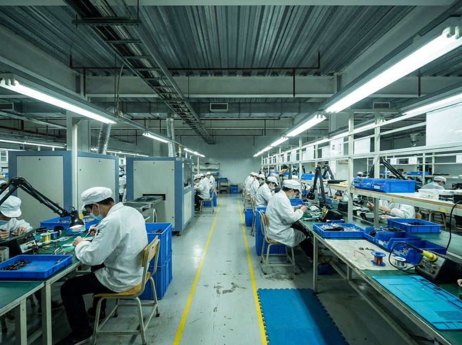
Odd-form parts, expensive devices and anything fitted after the main soldering step are done by hand. Locating fixtures and clamps are made from your drawing first, so insertion height, orientation and spacing come out the same on every board. Iron temperature, tip type and dwell time per joint are written into the work instruction, and stations are checked and logged at the start of each shift, so the result does not depend on who is on the bench.
Hand-soldered joints are inspected one by one for fillet formation, wetting, bridging and icicles, under magnification where the part warrants it. Rework has its own station, with BGA and IR rework equipment. Reworked boards go back through inspection and the number of rework cycles on that board is recorded.
ESD control and process discipline
The floor is temperature and humidity controlled and ESD-controlled. Benches carry grounded mats, operators wear wrist straps and ESD coats, and irons and instruments are checked for grounding and tip temperature on a schedule. Material moves by batch with a route card attached to the work order. Insertion, soldering and inspection are each signed off, so a board can be traced back to its operator, its equipment and its material batch.
Conformal coating
Boards going into humid, dusty or corrosive environments can be conformal coated, by brush, spray or selective dispensing depending on the layout. Connectors, sockets, test points and heatsink faces are masked with fixtures or tape before coating, and cure time follows the material datasheet. After cure the film is checked for even coverage, pooling, bubbles and missed areas. Name the coating material and thickness you want on the RFQ, mark the keep-out areas on the assembly drawing, and the masking will be built to them.
Capability
| Soldering methods | Wave soldering, selective soldering, hand soldering |
| Board formats | Pure through-hole, single-sided SMT plus through-hole, double-sided SMT with secondary soldering |
| Board types | FR-4, aluminium (MCPCB), ceramic, Rogers, flex, rigid-flex |
| Fixtures | Locating fixtures, wave pallets and masking fixtures, made in-house for your board |
| Rework | BGA rework and IR rework at a dedicated station |
| Surface protection | Conformal coating by brush, spray or selective dispensing, with masked keep-out areas and controlled cure |
| Solder alloy | SAC305 lead-free as standard; tin-lead where you specify it. |
| Inspection and test | Visual inspection, AOI, X-ray, ICT, flying probe, FCT |
| Workmanship | Boards are built to the IPC-A-610 acceptance class you specify |
| Workshop | Temperature and humidity controlled, ESD-controlled floor |
For a quotation, send us your Gerber, BOM and pick-and-place files — we reply within one working day.